Ultimate Guide to VFD Pump Control Systems
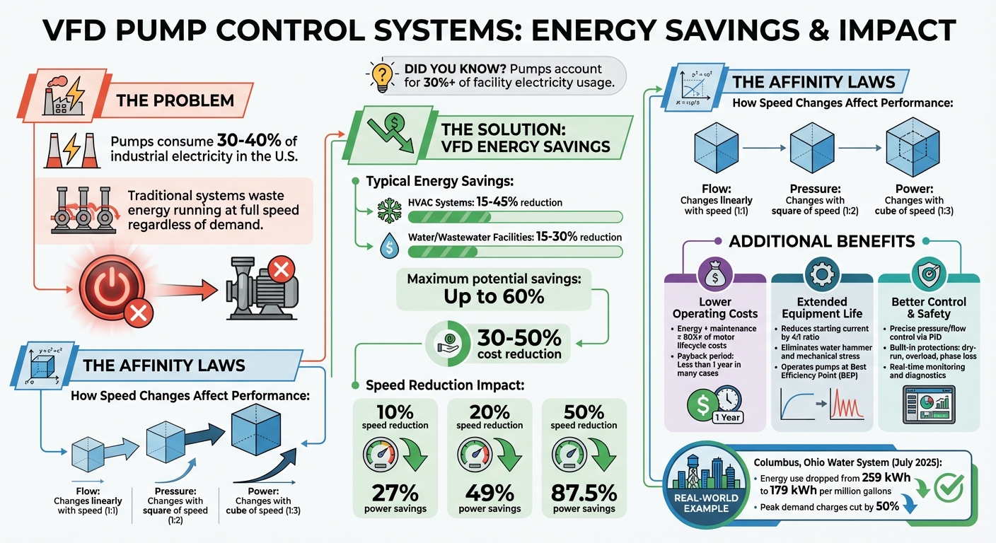
Did you know? Pumps consume over 30% of the electricity in U.S. industries, yet much of this energy is wasted when pumps run at full speed, regardless of demand. Variable Frequency Drives (VFDs) are a game-changer, reducing energy costs by 30-50% by adjusting motor speeds to match real-time needs.
Key Takeaways:
- What is a VFD? A device that controls motor speed by altering power frequency and voltage, offering precise flow and pressure control.
- Why it matters: VFDs save energy, reduce wear on equipment, and minimize maintenance costs by avoiding mechanical stress and pressure surges.
- Applications: HVAC, water systems, irrigation, and industrial processes like chemical dosing and wastewater management.
- Energy savings: A 10% speed reduction can cut power use by 27%, with potential savings of up to 60%.
- How it works: Sensors and PID controllers ensure pumps operate efficiently and safely, adjusting speed based on demand.
- Benefits: Lower energy bills, extended equipment life, and improved system reliability.
By using VFDs, facilities can significantly cut operating costs and improve the longevity of pump systems. Keep reading to learn how they work, where they’re used, and how to choose the right one for your needs.
VFD Energy Savings and Efficiency Statistics for Pump Systems
How Variable Frequency Drives Work in HVAC Systems
sbb-itb-99db659
How VFD Pump Control Systems Work
Understanding how a Variable Frequency Drive (VFD) operates in pump systems is crucial for optimizing installation, maintenance, and troubleshooting. At its core, a VFD transforms standard AC utility power into a variable-frequency, variable-voltage output, allowing precise control over motor speed. This process unfolds in several stages, with each component playing a specific role. Let’s break it down further.
Main Components of a VFD System
A VFD system includes four primary components that work together seamlessly:
- Rectifier: Converts the incoming constant-frequency AC power into direct current (DC) power.
- DC Bus: Filters and smooths the DC power before it moves to the next stage.
- Inverter: Takes the DC power and converts it back into variable-frequency AC using pulse-width modulation (PWM).
- Control System: Oversees the entire operation, processing inputs from manual controls (like keypads or dials) and automatic feedback from sensors.
| Component | Primary Role |
|---|---|
| Rectifier | Converts AC to DC |
| DC Bus | Filters and smooths the DC voltage |
| Inverter | Converts DC to variable-frequency AC using PWM |
| Control System | Processes sensor feedback and regulates output logic |
These components form the backbone of a VFD, but the integration of sensor feedback takes its performance to another level.
How Sensors Enable VFD Control
Sensors play a pivotal role by continuously monitoring variables like pressure, flow, and liquid levels. This real-time feedback is processed by an integrated PID (Proportional-Integral-Derivative) controller, which adjusts the pump speed to match system demands. For instance, in a building’s water distribution system, a pressure sensor measures pressure at key points. If demand drops – say, during nighttime hours – the sensor signals the VFD to slow the pump, ensuring consistent pressure without wasting energy.
Jason Vrboncic from WVCC Inc. highlights the importance of this integration:
“VFDs are best used when paired with control systems and operate best when based on a target flow rate measured by a flow sensor.”
Beyond efficiency, sensors also enhance safety by detecting potentially damaging conditions like dry-running. In such cases, the VFD can automatically shut down the pump, protecting equipment and eliminating the need for traditional mechanical throttling valves.
Understanding the Affinity Laws
The Affinity Laws provide the foundation for understanding how VFDs achieve energy savings. These laws explain how changes in motor speed affect centrifugal pump performance – specifically flow, pressure (or head), and power consumption . Here’s a quick summary:
- Flow changes linearly with speed.
- Pressure changes with the square of the speed.
- Power consumption changes with the cube of the speed.
For example, reducing motor speed by 20% results in a 20% decrease in flow, a 36% reduction in pressure, and a 49% drop in power consumption. Tom Neuberger, Product Manager at Eaton, explains:
“The affinity laws can determine the system performance for centrifugal devices, defining both theoretical load requirements and possible energy savings.”
| Affinity Law Relationship | Mathematical Formula |
|---|---|
| Flow vs. Speed | Q₁ / Q₂ = N₁ / N₂ (linear relationship) |
| Pressure vs. Speed | H₁ / H₂ = (N₁ / N₂)² (square relationship) |
| Power vs. Speed | P₁ / P₂ = (N₁ / N₂)³ (cubic relationship) |
This cubic relationship is why VFDs are so effective at reducing energy consumption. For example, cutting motor speed by 50% can slash power demand to just 12.5% of full capacity, resulting in an impressive 87.5% energy savings . These principles make VFDs particularly useful for applications with variable torque loads, such as HVAC systems, water distribution, and centrifugal pumps.
Benefits of Using VFDs in Pump Systems
VFDs (Variable Frequency Drives) offer more than just motor speed adjustments – they bring advantages in energy efficiency, equipment durability, and system control.
Energy Savings and Lower Operating Costs
One of the standout benefits of VFDs is their ability to drastically cut energy consumption. Pumps powered by motors account for 30–40% of industrial motor electricity use. Traditional systems run motors at full speed, wasting energy by restricting flow mechanically. VFDs address this inefficiency, reducing energy costs by as much as 60% in some cases. Typical savings range from 15% to 45% in HVACR systems and 15% to 30% in water and wastewater facilities.
Alex Harvey, Director of AC and DC Drives at Control Techniques – Americas, highlights this:
“In centrifugal pump applications with low head pressures, VFD controllers will typically save more than 50 percent of the energy used.”
Even small adjustments make a big difference – a 10% speed reduction can lower power usage by approximately 27%, with larger reductions leading to even greater savings.
Another benefit is the elimination of power spikes during motor startup. Traditional starting methods can draw up to 600% of the rated current, but VFDs use soft starts to gradually increase voltage and frequency, reducing the starting current by a 4:1 ratio. Since energy and maintenance make up over 80% of a motor’s life cycle costs, these savings directly impact operating expenses.
Longer Equipment Life
VFDs not only save energy but also extend the lifespan of equipment by reducing mechanical stress. Traditional motor starts create high inrush currents and shock loads, which can damage pumps, motors, and piping. VFDs, on the other hand, use S-ramp functions for smooth acceleration and deceleration, preventing mechanical shock and avoiding issues like water hammer – pressure surges caused by abrupt flow changes.
Operating pumps at their Best Efficiency Point (BEP) further reduces vibration, which is a major cause of wear. Alex Harvey explains:
“Variable speed control operates the pump at its BEP to greatly reduce vibration when compared to other process control methods. This reduction in vibration significantly extends the life of the pump seals.”
Additional features like skip frequencies help avoid speeds that trigger natural resonances, while sleep mode halts the pump during low-flow conditions to minimize wear. For pumps already spinning from backpressure, the flying start feature allows VFDs to safely regain control without stressing the impellers.
Better System Control and Safety
VFDs also enhance precision and safety, thanks to integrated control features. Closed-loop control systems can directly connect sensors for pressure, flow, or temperature to the drive’s PID controller. This setup allows the motor to adjust speed automatically, maintaining exact setpoints even when demand fluctuates. Such precision is critical for applications like chemical dosing, filtration, and water supply in high-rise buildings.
Torben Poulsen, Business Development Manager at ABB, underscores this benefit:
“Process control is about getting what is needed at any point in time. The user might need a certain pressure independent of the flow… Using a VFD and the right sensors makes it possible for the user to control the process in the way they want.”
Modern VFDs also come equipped with safety features that protect both equipment and operators. They monitor electrical and thermal conditions, detecting issues like short circuits, phase loss, ground faults, overloads, and voltage irregularities. Dry-run protection shuts down the pump when no fluid is detected, safeguarding seals and motors from damage. Advanced drives can even ride through temporary power losses, ensuring uninterrupted operation. Additionally, integrated communication protocols like Modbus and Ethernet, along with HMI panels, provide real-time data on energy use and performance, allowing for proactive maintenance.
How to Select the Right VFD
Once you understand how Variable Frequency Drives (VFDs) work and their advantages, the next step is choosing the right one for your application. This decision goes beyond just horsepower ratings – it requires careful consideration of motor specs, operating conditions, and the specific demands of your pump system.
Matching VFDs to Pump and Motor Specifications
To start, ensure the VFD’s output current and voltage align with your motor’s Full Load Amperage (FLA) and nameplate details. For demanding applications like deep well pumps, it’s smart to add a 10–20% safety margin to the motor’s FLA for additional reliability.
The type of pump you’re using also affects the VFD requirements. Centrifugal pumps, which are variable torque loads, typically need VFDs rated for 110–120% overload for up to 60 seconds. On the other hand, positive displacement pumps require constant torque and higher starting power, meaning you’ll need a VFD that can handle 150% overload. If your motor operates on a 480V system, confirm that it’s “inverter-duty” rated, meeting NEMA MG1 Part 31 standards, to handle voltage spikes effectively.
Another factor to consider is cable length. When the distance between the VFD and motor exceeds 200 feet – common in well pump setups – you should use output filters like load reactors or sine wave filters. These prevent reflected wave issues that can damage motor insulation.
Environmental and Operating Conditions
The environment where the VFD operates can significantly impact its performance and lifespan. Most drives are designed for ambient temperatures up to 40°C or 50°C. If temperatures exceed these levels, derating the VFD by around 1% per degree Celsius is necessary. Raj L. Narayanan, Product Manager at Eaton, highlights the importance of environmental factors:
“As with many electronic devices, environmental conditions can be a key factor in life span and reliability; temperature, humidity, shock and vibration, sun load, air cleanliness and quality are all factors that can affect the expected life span of VFDs.”
Choosing the right enclosure is also critical. For clean, indoor environments, an IP20 enclosure works well. For areas with light dust or humidity, opt for IP54/IP55-rated enclosures. Outdoor or harsh environments, such as those exposed to water or corrosive chemicals, require IP66/IP68 or NEMA 4X-rated enclosures.
In especially corrosive environments, like wastewater treatment plants or chemical facilities, adding a conformal coating to the VFD’s circuit boards can protect against harmful airborne chemicals like hydrogen sulfide or chlorine. If the VFD is installed outdoors, consider solar heat gain. White enclosures absorb less heat (with a heat gain coefficient of about 0.15) compared to black ones (0.97). Using sun shields or orienting the enclosure to reduce direct sunlight can also help.
Load and Performance Requirements
Understanding your pump’s performance needs is crucial for selecting the right VFD. For basic speed control in centrifugal pumps, the traditional V/Hz (Volts per Hertz) mode is usually sufficient and straightforward to set up. However, if you need precise control over flow or pressure – or if high starting torque is required in deep well systems – sensorless vector control can provide better low-speed torque and speed accuracy.
Sizing the VFD correctly is another key step. Oversizing wastes energy and efficiency, while undersizing can lead to overheating or early equipment failure. Even minor speed adjustments can noticeably reduce power consumption, making proper sizing essential for both performance and energy savings.
Finally, don’t overlook pump-specific protection features. For instance, dry-run protection is critical for well pumps to avoid motor damage when water levels drop. Similarly, sleep/wake logic in booster systems can save energy by shutting down the pump during periods of low demand.
Installation and Maintenance Guidelines
Ensuring proper setup and upkeep of a VFD (Variable Frequency Drive) is key to keeping it running efficiently.
Proper Installation Procedures
Start by confirming that the motor is “inverter duty” rated and complies with NEMA MG-1 Part 31 standards, which ensure it can handle VFD peak voltages. Check the cable insulation resistance – it should exceed 1 megohm at 68°F.
Mount the VFD on a flat, stable surface, free from vibrations, and leave at least 6 inches of clearance around it. Sean Gaffney, Senior Product Manager at VACON, emphasizes the importance of proper ventilation:
“Drives, like people, keep cool by ‘breathing.’ Failure to follow the instructions will result in a drive that does not operate properly, repeatedly trips on over-temperature faults and fails prematurely.”
When wiring, keep power cables and control cables in separate conduits to minimize electromagnetic interference. If they must cross paths, ensure they do so at a 90-degree angle. Use shielded cables for motor connections, and always connect both the VFD and motor to a robust earth ground. Additionally, install the manufacturer-recommended fuses on the incoming line side. As Gaffney points out, “A drive measures and monitors itself and its motor outputs, but a drive does little to protect itself against incoming voltage or current spikes”.
Before powering up, torque all terminal connections according to the manufacturer’s specifications. On initial startup, use the “jog” function to check motor rotation. If the direction is incorrect, swap two output connections. Once the motor is correctly aligned, run the drive’s auto-tune or motor-identification function. This step ensures the VFD can create an accurate motor profile, enhancing control and protection.
Once installation is complete, the focus shifts to ongoing maintenance to keep the VFD performing at its best.
Regular Maintenance Tasks
While VFDs are designed to operate for five to ten years without major intervention, regular inspections are essential. Annually, check for condensation, corrosion, dust, and insects. Clean heatsinks, fans, and filters to prevent blocked airflow, which can lead to overheating and early failures.
Power connections can loosen over time due to temperature fluctuations. Jason Wellnitz, Product Marketing Manager at Yaskawa America, Inc., highlights the risks:
“Power connections can loosen with heating and cooling cycles. Loose connections can overheat and cause VFD faults, tripped branch circuit protection, or premature failure.”
Use a torque wrench annually to ensure all connections meet OEM specifications. A thermal imaging camera can also help identify hot spots in wiring during peak operation, allowing you to address potential problems early.
If a VFD remains unused for over six months – whether in storage or during a seasonal shutdown – perform capacitor reforming. This involves gradually applying voltage through a variac to prevent damage to the capacitor’s dielectric material. Additionally, always keep a backup of the VFD’s parameter file on a memory card or cloud storage. This makes restoring settings quick and hassle-free if the drive fails.
Routine inspections and resolving faults promptly are crucial for extending the drive’s lifespan.
Performance Monitoring and Diagnostics
After maintenance, continuous monitoring helps catch issues before they escalate. Modern VFDs monitor their internal health, tracking parameters like power module and heatsink temperatures, capacitor conditions, and DC bus voltage ripple. Pay attention to fault codes – they can indicate whether the problem is electrical (e.g., overvoltage, undervoltage, phase loss) or mechanical (e.g., pump blockage or overload).
Set up SMS or email alerts for fault events to address issues quickly and avoid downtime. If you notice unusual vibrations or noise, gradually adjust the pump speed to identify problematic frequencies. Noise disappearing at lower speeds often points to cavitation.
For critical systems, don’t rely solely on the VFD’s internal flow calculations. Use a physical flow meter, such as a magnetic or ultrasonic type, for precise closed-loop PID control. As Jason IP P.E., a Professional Engineer at Industrial Monitor Direct, advises:
“You cannot control what you do not measure”.
Export trend data quarterly and log parameter changes to identify inefficiencies early.
VFD Optimization Techniques
Fine-tuning your Variable Frequency Drive (VFD) settings can significantly improve energy efficiency and system performance. When combined with proper installation and maintenance, these adjustments can lower energy costs and enhance system reliability.
Closed-Loop Control with Sensors
Using real-time sensor feedback to configure your VFD ensures optimal pump performance. Rather than running at a constant speed and relying on valves to regulate flow, closed-loop control adjusts motor speed based on actual demand. Sensors like pressure transducers, flow meters, or level sensors provide continuous feedback to the VFD, which maintains the desired setpoint with precision.
When setting up PID parameters, start with conservative gains and gradually increase the integral time. This approach minimizes “hunting” – the oscillations around the setpoint that waste energy and strain equipment.
Closed-loop systems also support sleep mode, where the VFD shuts off the pump during zero-demand periods. In constant pressure systems, a pressurized tank (hydrophore) maintains pressure while the pump rests, avoiding inefficiencies from running against a closed valve. As Torben Poulsen, Business Development Manager at ABB, explains:
Just a small decrease in speed will decrease the power consumption considerably. It is known from the affinity laws that a 10% reduction in speed will lead to a 27% reduction in power.
For systems with multiple pumps, optimizing how they work together can further improve efficiency.
Multi-Pump Staging and Load Sharing
In setups with multiple pumps, automated staging ensures pumps operate near their most efficient point. Additional pumps are activated only when demand surpasses the lead pump’s capacity and are turned off as demand decreases. This method keeps each pump closer to its Best Efficiency Point (BEP), avoiding inefficiencies caused by running oversized pumps at low speeds.
There are two common configurations for multi-pump systems: one VFD controlling a single variable-speed pump with fixed-speed auxiliaries, or multiple VFDs where a master drive coordinates all follower drives. Ideally, each pump should have its own VFD for better performance and redundancy. Ranbir (Ron) Ghotra, Lead Application and Systems Engineer at Eaton, highlights the benefits:
Achieving this degree of control and automation by just using the VFD cuts down the installation and commissioning time for the pumping system and improves the overall return on investment (ROI).
To evenly distribute wear across equipment, program VFDs to rotate the lead pump based on runtime. For periods of low demand, consider adding a smaller jockey pump with its own VFD instead of running a large pump inefficiently. Rebekah Macko from Geiger Pump & Equipment explains:
A small pump with its own VFD for low demand can offer better efficiency and overall system reliability than a large pump sized for peak demand operating back on its curve.
In wastewater systems, always maintain a minimum speed high enough to keep self-cleaning velocity in pipes, preventing solids from settling.
Once pump operations are coordinated, refining control parameters can lead to even greater energy savings.
Programming for Maximum Energy Efficiency
Properly programming VFD parameters can unlock significant energy savings. Set acceleration and deceleration ramps to around 10 seconds to minimize inrush current and reduce mechanical stress on components like couplings, bearings, and seals. A minimum speed between 30% and 50% of nominal ensures the pump remains above its minimum continuous stable flow while still achieving energy savings.
With closed-loop control in place, mechanical throttling can often be reduced or eliminated. As Rebekah Macko notes:
VFDs often allow control valves to be more open than constant speed systems because the pump can be slowed down to achieve the same flow rate with less throttling, leading to energy savings.
In some cases, minimum flow orifices can be removed entirely.
For tank-fed systems, program the VFD to slow the pump when supply tank levels drop. This prevents cavitation when Net Positive Suction Head available (NPSHa) is limited and reduces wasted energy. Additionally, use the VFD’s internal data logs to monitor energy use, starts, and operating hours. This data can help identify opportunities to refine setpoints and schedules even further. Typical energy savings from these programming strategies range from 15% to 45% in HVAC systems and 15% to 30% in water and wastewater applications.
Conclusion
VFD pump control systems offer a powerful way to lower energy expenses and extend the lifespan of equipment. For instance, reducing pump speed by just 10% can decrease power consumption by 27%. Some facilities have even reported energy savings of up to 60%, with payback periods of less than a year. Considering that pumps often account for over 30% of a facility’s total electricity usage, the potential for significant annual savings is clear.
By combining advanced components, precise controls, and smart optimization strategies, VFD systems bring numerous advantages. Soft starts help avoid the damage caused by high inrush currents and water hammer, protecting seals, bearings, and pipes. Real-time speed adjustments ensure pumps operate under ideal conditions, preventing issues like cavitation. Additionally, built-in diagnostics can identify problems early, reducing both downtime and maintenance costs.
The versatility of this technology is evident across various applications. HVAC systems, for example, have achieved energy savings ranging from 15% to 45%. Municipal water systems also showcase its effectiveness – take Columbus, Ohio’s July 2025 retrofit as an example. After implementing VFDs, specific energy consumption dropped from 259 kWh to 179 kWh per million gallons, and peak demand charges were cut in half.
With tangible benefits like lower utility bills, reduced maintenance, and enhanced process control, VFD pump control systems deliver quick returns on investment. They’ve become an indispensable part of modern pumping solutions.
FAQs
How do I know if my pump is a good fit for a VFD?
To figure out if your pump works well with a VFD, start by assessing its operating conditions. Pumps that deal with variable load demands, energy inefficiencies, or frequent on-off cycles are prime candidates. Applications like water supply, HVAC systems, or irrigation often involve fluctuating demand, making them a good match for VFDs. Centrifugal pumps, in particular, pair well when you need precise flow control and better energy savings. Just make sure your pump is designed to handle variable speed control for the best performance.
What sensors are needed for closed-loop VFD pump control?
Closed-loop VFD pump control relies heavily on flow meters to measure flow rate (in GPM) and pressure sensors to track system pressure. These two components feed crucial data into the VFD’s control algorithms, such as PID controllers, allowing for real-time adjustments to pump speed. While additional sensors – like those for temperature or motor current – can help monitor overall system health, the flow meters and pressure sensors remain the core elements for maintaining efficient operation.
When should I add output filters for long motor cable runs?
When motor cables are particularly long, it’s important to include output filters. Why? Extended cables can lead to voltage spikes, ringing, and even insulation breakdown, all caused by impedance mismatches. These longer cables tend to amplify overshoot peak voltage, which could harm both the motor and the VFD. By adding output filters, you can help safeguard the system, ensuring smoother operation and reducing the risk of damage.