10 Tips to Prevent Plumbing Leaks
Plumbing leaks can lead to expensive repairs, water waste, and even structural damage. The good news? Most leaks are preventable with simple maintenance and upgrades. Here are 10 ways to protect your plumbing system and avoid costly problems:
- Control water pressure: Keep it between 40-60 PSI to prevent pipe strain.
- Insulate pipes: Protect pipes in cold areas to avoid freezing and bursting.
- Upgrade toilet parts: Replace worn flappers and fill valves to stop silent leaks.
- Fix dripping faucets: Address worn seals or mineral buildup to save water.
- Clean gutters: Prevent water pooling near your home’s foundation.
- Schedule inspections: Professional plumbers can catch hidden issues early.
- Use steel hoses: Replace rubber washing machine hoses with durable steel ones.
- Install ball valves: Make shutting off water during emergencies quick and easy.
- Reapply caulk and grout: Seal gaps around fixtures to keep water out of walls.
- Add leak detection systems: Get alerts for leaks and stop water damage fast.
These steps combine DIY care with professional expertise to safeguard your home or business from leaks. Regular maintenance not only prevents damage but also saves on water bills and repair costs.
How to Prevent Household Plumbing Leaks | This Old House

1. Keep Water Pressure Between 40-60 PSI
Did you know that water pressure above 60 PSI can strain your plumbing system and increase the likelihood of leaks? While a powerful shower might seem tempting, excessive pressure takes a toll on your pipes, fixtures, and valves, leading to wear and tear over time.
High water pressure can create weak spots in your plumbing, which may eventually rupture and cause expensive water damage. To keep your system in good shape, aim for water pressure between 40-60 PSI. This range provides enough flow for daily activities without overburdening your pipes. If your pressure climbs above 80 PSI, it’s considered hazardous and needs immediate attention.
How to Check Your Water Pressure
Checking your water pressure is easier than you might think. Pick up an affordable pressure gauge from a hardware store and attach it to an outdoor faucet or the one closest to your main water line. Turn on the water and read the gauge.
If the pressure measures above 80 PSI, your plumbing could be at risk. Even readings between 60-80 PSI can cause unnecessary strain and should be addressed promptly.
Warning Signs of High Pressure
High water pressure often announces itself with some noticeable symptoms. For example, you might hear loud banging or hammering noises in your pipes – this is called “water hammer” and happens when high-pressure water creates shockwaves. Other signs include faucets spraying unevenly, fixtures wearing out faster than usual, and frequent leaks at pipe joints or appliance connections.
Installing a Pressure Regulator
A pressure regulator is a simple yet effective solution to keep your water pressure within the safe 40-60 PSI range. Installed on your main water line, it automatically adjusts the pressure entering your home. It’s best to have a professional handle the installation to ensure it’s placed correctly near your water meter. The upfront cost is minor compared to the price of repairing burst pipes or fixing major leaks. After installation, these devices require only occasional checks to ensure they’re working as intended.
If DIY plumbing isn’t your thing, companies like Hydrodynamics Inc. offer professional services to help you maintain safe water pressure and protect your plumbing system.
The Financial Upside
Keeping your water pressure in check doesn’t just protect your pipes – it can also save you money. Operating within the 40-60 PSI range reduces water waste during everyday use, which can lower your water bills. Over time, the combination of reduced water usage and fewer repair costs makes pressure regulation a smart investment.
Up next: Discover how insulating your pipes can add another layer of protection to your plumbing system.
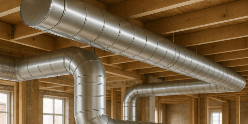
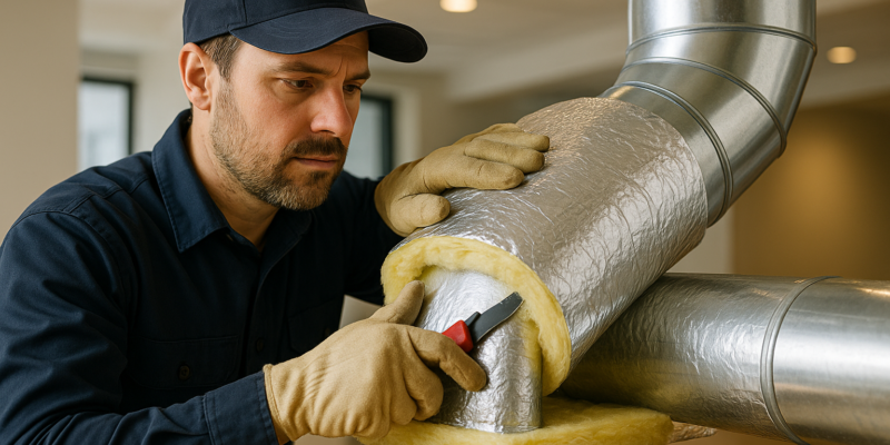
2. Insulate Pipes in Cold Areas
When the temperature plunges, pipes in unheated areas can become a major problem. As water freezes, it expands, creating pressure that can cause pipes to burst – leading to thousands of dollars in water damage. The most at-risk locations include basements, crawl spaces, attics, garages, and any pipes running along exterior walls or near windows. Even a brief cold snap can freeze exposed pipes if they’re not adequately protected. Alongside managing water pressure, safeguarding your pipes from freezing is key to avoiding leaks.
Why Pipe Insulation Is Effective
Pipe insulation – or lagging – helps prevent the freeze-thaw cycle that can damage pipes. It also keeps hot water warmer for longer, improving energy efficiency. Just like maintaining proper water pressure, insulating your pipes is an essential step in preventing leaks.
Choosing the Right Insulation
You’ve got two main tools to protect your pipes: foam pipe insulation and heat tape.
- Foam pipe insulation: This is a budget-friendly option, with costs ranging from $0.50 to $2.00 per linear foot. Foam sleeves wrap snugly around pipes, acting like a thermal barrier against cold air. For homes with 100 to 150 feet of exposed pipes, you’re looking at material costs of roughly $50–$300.
- Heat tape: This electric solution actively warms pipes, making it ideal for extreme cold or highly exposed areas. Heat tape typically costs between $1.00 and $3.00 per linear foot. For maximum protection, you can combine both methods – use foam insulation as a base and add heat tape for extra security.
While the upfront costs vary based on the length of your pipes, they’re minimal compared to the cost of repairing burst pipes, which can climb anywhere from $5,000 to $25,000 or more.
Spotting Vulnerable Pipes
Grab a flashlight and check your home’s unheated spaces. Start in the basement and crawl spaces, then move to the attic. Pay close attention to pipes near windows, exterior walls, or particularly chilly corners. Follow your water supply lines from where they enter your home, checking any unheated areas along the way. Don’t forget to inspect pipes in the garage or near exterior doors. In colder regions, all exposed pipes need insulation, while in milder climates, focus on the most vulnerable spots.
Installing Foam Insulation
Installing foam insulation is simple and effective. Start by measuring the diameter of your pipes and purchasing foam sleeves that fit snugly. Wrap the foam around the pipes, securing it with tape or zip ties. Use a utility knife to trim the foam for corners or joints. Be thorough – any exposed section, no matter how small, is at risk of freezing. For hard-to-reach areas or if you’d rather leave it to the pros, companies like Hydrodynamics Inc. can handle the installation for you.
Adding Heat Tape for Extra Security
Heat tape offers an extra layer of protection in extreme cold. Wrap it around the pipe as per the manufacturer’s instructions. Some types need to be spiraled around the pipe, while others run straight along its length. Make sure the tape is plugged into a nearby outlet for it to work properly. Never overlap heat tape unless the instructions explicitly say it’s safe – overlapping can create hot spots, which might damage the tape or even pose a fire risk.
Quick Tips for Cold Snaps
During particularly cold weather, a few simple steps can help protect your pipes. Keep garage doors closed if water lines run through the space, let faucets connected to exposed pipes drip slightly, and open cabinet doors under sinks to let warm air circulate around the pipes.
Keeping Your Insulation in Check
Once your pipes are insulated, make it a habit to check the insulation periodically, especially after severe weather. Look for gaps or areas where the material might have shifted or come loose. Foam insulation is designed to stay in place year-round, even in unheated spaces. When freezing temperatures subside, disconnect and store heat tape. Before the next winter season, inspect your pipes for damage and ensure the insulation is still intact.
Next, learn how upgrading toilet components can further reduce the risk of leaks.
3. Replace Old Toilet Parts
Your toilet could be quietly wasting water without you even noticing. Worn-out parts like the rubber flapper or a failing fill valve are often the culprits. The good news? Fixing these issues is simple and won’t break the bank.
Common Culprits: Flappers and Fill Valves
The rubber flapper sits inside your toilet tank, sealing the drain between flushes. Over time, exposure to water and chlorine can cause it to harden, crack, or lose its shape. When this happens, water escapes from the tank into the bowl nonstop. You might hear a faint hissing sound or notice your toilet randomly refilling itself.
The fill valve, also called the refill valve, controls how water flows into the tank after you flush. When it starts to fail, you may notice the tank struggling to fill or the toilet running long after you’ve flushed.
How to Detect a Problem
If you hear constant trickling or spot food coloring in the toilet bowl after 15–20 minutes of testing, you’ve got a leak. Other warning signs include weak flushes, inconsistent water levels, or visible wear on the flapper.
These silent leaks can waste about 200 gallons of water each day – that’s 6,000 gallons in a month or a staggering 73,000 gallons in a year. Depending on your water rates, this could inflate your annual bill by $100–$300 or more.
A Quick DIY Fix
Replacing a toilet flapper is one of the easiest plumbing tasks you can handle yourself. A new flapper costs under $10, and the entire job takes just 15–30 minutes. Fill valves are slightly more expensive, ranging from $15–$30, but they’re just as beginner-friendly.
To replace the flapper, turn off the water supply, flush to empty the tank, remove the old flapper, and attach the new one. Turn the water back on and test a few flushes to ensure everything works properly.
For a fill valve replacement, you’ll need an adjustable wrench. Shut off the water, drain the tank, disconnect the water supply line, and unscrew the old valve. Follow the manufacturer’s instructions to install the new valve, reconnect everything, and check for leaks.
When to Call a Professional
If replacing the flapper doesn’t solve the issue, other components could be at fault. A broken fill valve, loose gasket, corroded bolt, or damaged flush valve seat might be to blame. Water pooling at the base of your toilet could indicate a broken wax seal or cracked porcelain – both of which require professional attention.
For complex repairs or commercial properties, consider hiring experts like Hydrodynamics Inc. They can quickly diagnose and fix leaks while ensuring the system complies with building codes.
Keeping Your Toilet in Top Shape
Make toilet checks a regular part of your home maintenance routine. Inspect the flapper every few months – if it feels stiff or brittle, replace it before it fails.
Avoid using harsh chemical cleaners, which can accelerate wear on rubber parts. If you live in an area with hard water, mineral buildup can damage seals and valves. Installing a water conditioner can help extend the life of these components.
And while you’re at it, take a moment to address any dripping faucets or showerheads to further reduce water waste.
4. Fix Dripping Faucets and Showerheads
A dripping faucet isn’t just annoying – it’s costly. A single drip can waste about 3,000 gallons of water every year. Over time, this can translate into hundreds or even thousands of dollars added to your water bill. Just like keeping an eye on water pressure and insulating pipes, fixing small leaks in faucets and showerheads is an important step in protecting your plumbing system.
What’s Causing the Drip?
The usual culprits behind dripping faucets and showerheads are worn-out internal parts that compromise the seal. Hard water can also leave mineral deposits inside aerators or around internal components, leading to restricted water flow and damaged seals. For showerheads, leaks often stem from loose connections or deteriorated washers and O-rings.
Simple Fixes You Can Do Yourself
Before calling in a professional, there are a few easy repairs you can try at home. These quick fixes, paired with regular maintenance, can help you avoid expensive leaks.
- Replace worn parts: Swap out washers, gaskets, or O-rings that are old or damaged. These are inexpensive and widely available.
- Clean mineral buildup: Remove your faucet’s aerator and soak it in vinegar to dissolve any deposits.
- Tighten loose connections: For a leaky showerhead, wrap Teflon tape around the pipe threads and use a wrench to tighten the connection. If that doesn’t work, replace the washer or O-ring and soak the showerhead in vinegar to clear any blockages caused by mineral deposits.
When to Call for Help
If the drip persists even after replacing parts and tightening connections, the problem might be more complex than it seems. In such cases, it’s best to contact a professional plumber. Experts, like those at Hydrodynamics Inc., can quickly diagnose and resolve the issue, helping you avoid bigger problems and keeping your water bills in check.
Keep Your Fixtures in Good Shape
Routine maintenance is key to preventing leaks before they start. Check that faucet and shower handles close completely, and monitor your water pressure to ensure it stays within the recommended range of 40 to 60 PSI. Higher pressures can strain pipes and fixtures, so installing a water pressure regulator is a smart move. Acting quickly on repairs and maintaining your fixtures regularly can save you from costly water damage and keep your plumbing system running smoothly.
5. Clean Gutters and Drainage Systems
Clogged gutters and poor drainage can lead to water pooling around your foundation and exterior walls. This buildup increases hydrostatic pressure, which can result in leaks. Addressing this external issue works hand-in-hand with the internal maintenance steps mentioned earlier.
How Water Gets Into Your Plumbing
When gutters fail to direct water away from your home, it collects near the foundation and seeps into the soil. Over time, this moisture can find its way into weak spots in your plumbing. Constant exposure to water can corrode pipes, weaken seals, and compromise the overall integrity of your plumbing system.
The Right Way to Clean Your Gutters
You don’t need fancy tools to maintain your gutters – just a bit of effort. Start by removing debris like leaves, twigs, and dirt using a scoop or your hands (make sure to wear gloves). Next, flush out the gutters with a garden hose to clear any remaining buildup and ensure proper water flow. While you’re at it, inspect the downspouts to confirm they’re free of blockages. It’s crucial that downspouts direct water at least 4 to 6 feet away from your foundation – dumping water too close can create the same problems as clogged gutters.
How Often Should You Clean?
Plan to clean your gutters at least twice a year. If your home is surrounded by trees, you might need to do this quarterly. In areas with heavy rainfall or during winter (when ice dams can form), more frequent checks can help prevent blockages. After severe storms or strong winds, inspect your gutters for damage or debris buildup.
Warning Signs Your Drainage Is Failing
Be on the lookout for water pooling near your foundation or stains appearing in your basement. Other red flags include musty odors in crawl spaces, soil erosion around your property, or downspouts that don’t effectively move water away from the building. If you’re dealing with recurring plumbing leaks and can’t pinpoint an internal cause, poor exterior drainage might be the culprit.
Going Beyond Basic Gutters
For areas with heavy rainfall or limited drainage options, consider adding features like a French drain. A French drain is a trench filled with gravel and a perforated pipe designed to direct water away from problem areas. This addition can significantly improve water management and reduce the risk of leaks.
Building a Complete Prevention Strategy
Pairing regular gutter cleaning with professional plumbing inspections ensures all your water management systems are working effectively. Companies like Hydrodynamics Inc. can provide detailed drainage system evaluations and recommend solutions tailored to your property, whether it’s residential or commercial.
Integrating these drainage strategies with your ongoing plumbing upkeep will create a strong defense against leaks and water damage.
sbb-itb-99db659
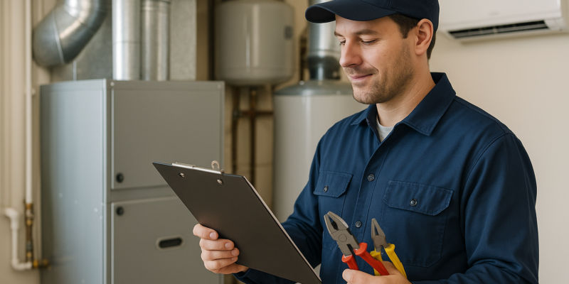
6. Get Regular Professional Plumbing Inspections
Monthly DIY checks are great for catching surface-level issues, but when it comes to spotting hidden problems, licensed plumbers have the tools and training to go deeper. From checking water pressure to inspecting pipe insulation, regular professional plumbing inspections are key to catching leaks early – before they become costly disasters.
How Often Should You Schedule Inspections?
Plan for a full-system inspection once a year, with quarterly checks for high-risk areas like bathrooms, kitchens, and laundry rooms. If your home has older plumbing, you’ll want to prioritize these inspections even more, as aging systems are more prone to corrosion and wear.
What Professional Plumbers Look For
Plumbers go beyond the obvious. They’ll check under sinks for leaks or moisture, inspect supply lines to faucets, dishwashers, and ice makers, and examine washing machine hoses for cracks or brittleness. They also review visible pipes for signs of corrosion, especially in unheated spaces like basements or near exterior walls where pipes are at risk of freezing.
During their inspections, they’re trained to spot early warning signs of trouble. Things like rust, mineral buildup, or water stains around fittings can indicate slow leaks or failing components. Even subtle issues like discoloration on exposed pipes or calcium buildup affecting water pressure can signal problems down the road. Advanced tools, like humidity sensors, help them detect hidden dampness behind walls – something homeowners can easily miss.
Why Professional Expertise Matters
DIY inspections can only take you so far. Skilled plumbers can identify hard-to-spot issues like tiny cracks or splits in pipes that might not be visible without a thorough evaluation. They’re also trained to detect deteriorating galvanized pipes, which can lose their zinc coating over time, leading to serious problems if left unchecked.
Advanced Detection and Prevention
Professional plumbers don’t just find leaks – they can help prevent them. They can install smart water monitors to track unusual usage patterns, WiFi-enabled leak detectors for high-risk spots like basements, and even whole-house shut-off systems you can control remotely. For added protection, they might recommend automatic shut-off valves or electric water sensors that stop leaks before they cause damage. Once these systems are in place, they’ll also ensure your plumbing is ready for seasonal changes.
Seasonal Maintenance Coordination
Speaking of seasons, plumbers can take care of tasks like winterizing outdoor faucets and checking pipe insulation ahead of colder months. These steps help protect your system from freezing and other seasonal challenges.
What to Expect from Your Inspection
A professional inspection should provide a detailed overview of your plumbing system’s health. This includes identifying leaks, suggesting repairs or upgrades, and documenting concerns with photos or notes. They’ll prioritize issues by urgency, estimate repair costs, and offer advice tailored to your home – like whether you need additional pipe insulation or more durable fixtures with ceramic disc valves.
Finding the Right Professional
When choosing a plumber, look for licensed professionals with experience in handling complex systems. Companies like Hydrodynamics Inc. offer a range of services, from simple repairs to full-scale maintenance and energy-efficient solutions for residential and commercial properties.
Building a relationship with a local plumber who knows your home’s plumbing system can make all the difference in preventing long-term issues. For businesses, setting up a dedicated maintenance schedule with a professional service ensures both leak detection and timely repairs.
Next, we’ll explore how upgrading to steel hoses for your washing machine can help prevent one of the leading causes of household flooding.
7. Use Steel Hoses for Washing Machines
Did you know that washing machines are a common culprit behind household water leaks? The main issue often lies with aging rubber hoses, which can develop weak spots over time due to constant pressure and temperature changes.
Why Upgrade to Steel Hoses?
Braided stainless steel hoses are a smart replacement for rubber hoses. They’re built to resist corrosion and can handle both high pressure and temperature fluctuations. Unlike rubber hoses that typically last only 3–5 years, steel hoses can go strong for over a decade. Upgrading to these durable hoses not only reduces the risk of leaks but also strengthens the vulnerable connection points of your washing machine. Combine this with regular inspections and proper water pressure management, and you’ve got yourself a solid leak prevention plan.
Are Steel Hoses Worth the Cost?
At first glance, steel hoses might seem pricier – costing anywhere from $15 to $40 per hose compared to the $5–$15 range for rubber ones. But think about this: a single washing machine leak can cause thousands of dollars in damage to your floors, walls, and personal items. With their longer lifespan and superior durability, steel hoses are a cost-effective investment in the long run.
How to Replace Your Hoses
Switching to steel hoses is a quick and simple task you can tackle yourself in about 10–15 minutes. Here’s how:
- Turn off the water supply.
- Disconnect the old rubber hoses.
- Clean the connection points thoroughly.
- Attach the new steel hoses, hand-tightening them first and then securing with a wrench.
- Turn the water back on and check for any leaks.
When shopping for steel hoses, look for ones designed for high-pressure use, with a burst rating of at least 500 PSI. Opt for hoses with stainless steel outer braiding, reinforced inner tubing, and corrosion-resistant fittings. If DIY isn’t your thing, a professional plumber – like those at Hydrodynamics Inc. – can install the hoses and inspect your connections during routine maintenance.
Maintaining Steel Hoses
To keep your steel hoses in top shape, inspect them once a year for any signs of wear, corrosion, or loose fittings. If you notice mineral buildup, wipe it away with a soft cloth to prevent leaks. Ready to take the next step? Learn how adding ball valves can make shutting off water in an emergency a breeze.
8. Install Ball Valves for Easy Water Shutoff
When a water leak happens, every second matters. The difference between a small inconvenience and a major disaster often depends on how fast you can stop the water flow. Ball valves are a reliable way to control water and quickly shut it off, serving as an essential part of your overall leak prevention plan.
Why Ball Valves Are Better Than Gate Valves
Unlike traditional gate valves that rely on rubber seals prone to wear and tear, ball valves use a rotating ball mechanism that creates a tight, long-lasting seal. This durability ensures they perform effectively during emergencies, making them a reliable choice for controlling water flow.
Placement Matters
Strategically placing ball valves throughout your plumbing system allows you to isolate specific problems without disrupting water supply to the rest of your home. Many plumbing fixtures already have stop valves, but upgrading these to ball valves is a smart move. Prioritize high-risk areas such as your main water line, under sinks, near toilets, at your water heater, next to your dishwasher, and especially by your washing machine – one of the most common sources of household leaks. Installing ball valves at these critical points ensures you can address leaks or issues with individual fixtures without shutting off water to your entire home.
The Cost and Benefits of Ball Valves
Uncontrolled leaks can lead to repair costs running into hundreds or even thousands of dollars, not to mention spiking your water bill. Investing in durable, full-port brass ball valves – designed for water pressure levels between 40–60 PSI – can save you from these expenses. Brass is an excellent choice because it resists corrosion and stands up well to wear. Make sure the valves you select are rated for your system’s specific water pressure to ensure optimal performance.
Maintaining Ball Valves for Longevity
While ball valves are more durable than gate valves, they still require occasional upkeep. Check them annually for signs of corrosion, mineral buildup, or leaks around the valve stem. If you notice moisture or dripping, it might mean the internal seal is failing, and the valve could need replacing. A simple way to keep them in good condition is to open and close them a few times a year – this prevents them from sticking due to mineral deposits or corrosion. During routine plumbing inspections, ask a professional to verify that your ball valves are ready to work when you need them most.
When to Bring in a Professional
Although some homeowners may feel comfortable installing ball valves themselves, hiring a professional plumber is often the best choice. Professionals ensure proper placement and compliance with local building codes. They can also assess your water pressure, pipe materials, and fixture types to recommend the best ball valves for your system. With their expertise, you can be confident your plumbing is set up for maximum efficiency and safety.
Ball valves are a practical addition to your home’s plumbing system, helping you manage leaks and minimize potential damage. Next, we’ll look at another important step: maintaining fixture seals to ensure water stays where it’s supposed to.
9. Reapply Caulk and Grout Around Fixtures
The caulk and grout around sinks, tubs, and showers play a crucial role in keeping water where it belongs. They prevent moisture from seeping into walls, subfloors, and other hidden areas. But over time, these seals can degrade due to constant exposure to water, temperature shifts, and daily use. When they fail, water can sneak behind fixtures, causing damage you might not notice until it’s too late.
Common Trouble Spots for Caulk and Grout
Failures often occur in high-moisture areas like tubs, showers, and under sinks. Key problem zones include where tiles meet fixtures and around faucet bases. If water finds its way into these gaps, it can lead to mold, mildew, and even wood rot.
How to Spot Issues Early
Regular inspections are key. Check your caulk and grout monthly for cracks, gaps, or signs of wear. Discoloration or dark spots often hint at mold or mildew, suggesting water has already breached the seal. If the caulk is pulling away from the surface or feels soft and spongy, it’s time to replace it. Other red flags include water stains on walls or ceilings below fixtures and dampness in cabinets or around the base of sinks and tubs.
Choosing the Right Materials
For wet areas like showers and kitchen sinks, silicone caulk is your best bet. It’s flexible, resists mold, and holds up against water and temperature changes. In less damp areas, acrylic latex caulk is easier to work with and clean. When it comes to grout, epoxy grout is a strong choice for high-moisture spaces because it offers better water resistance and durability than traditional cement-based grout.
Steps to Reapply Caulk
Reapplying caulk isn’t complicated if you follow a few simple steps:
- Start by removing the old caulk with a scraping tool.
- Clean and thoroughly dry the area.
- Apply painter’s tape along the edges for a clean line.
- Use a caulking gun to apply a steady bead along the joint.
- Smooth the caulk with a wet finger or tool for a neat finish.
- Allow 24–48 hours for it to cure completely.
Prevention Costs Less Than Repairs
Replacing caulk and grout is a small investment compared to the cost of repairing water damage. Materials for a DIY job typically run between $10 and $30, while hiring a professional might cost $100 to $300, depending on the scope of work. Compare that to the potentially thousands you’d spend fixing damage from a hidden leak, and it’s clear that regular maintenance is a smart move.
Boosting Protection with Technology
Adding smart leak detection systems to your home can provide an extra layer of security. Placing WiFi-enabled leak detectors under sinks, near tubs, and around other fixtures can alert you to water issues before they escalate. Some systems even include automatic shutoff features to stop water flow if a leak is detected.
When to Bring in the Experts
If you’re unsure about your caulk and grout or suspect hidden issues, it’s wise to call a professional. They can use tools like moisture meters and thermal imaging cameras to uncover problems you might miss. Experts can also recommend the best materials for your specific needs and handle the job if DIY isn’t your thing. For professional assistance, consider reaching out to Hydrodynamics Inc. for a thorough inspection and re-caulking service.
Up next, we’ll dive into how modern leak detection systems can further safeguard your home.
10. Add Leak Detection Systems
Leak detection systems are a practical solution to safeguard your property from water damage. These systems continuously monitor your plumbing and send alerts at the first sign of trouble. Whether you’re a homeowner or managing a business, they can help you avoid costly repairs and extensive damage.
How Leak Detection Systems Work
At their core, these systems use moisture sensors to detect leaks and issue alerts. Advanced models take it a step further by tracking real-time water usage and automatically shutting off the water supply when a leak is identified. This combination of monitoring and proactive response makes them a worthwhile investment.
Types of Systems to Consider
There’s a range of leak detection systems to fit different needs and budgets:
- Basic Moisture Sensors: Priced between $50 and $200, these are ideal for high-risk areas and provide simple alerts when moisture is detected.
- Smart Systems: With features like smartphone notifications and water usage tracking, these systems cost between $200 and $500.
- Comprehensive Systems: These monitor multiple areas, track water pressure, and detect temperature changes to identify potential issues.
If you opt for professional installation, expect to pay an additional $200–$500. While this might seem like an added expense, it’s minimal compared to the potential costs of water damage restoration, which can run into the thousands. For commercial properties, even a minor leak can lead to significant damage and disrupt operations.
Strategic Sensor Placement
To maximize the effectiveness of your leak detection system, place sensors in areas most prone to leaks. Common locations include:
- Under sinks and around water heaters
- Near washing machines and dishwashers
- In basements or crawlspaces where pipes are exposed
For commercial buildings, consider additional placement near HVAC systems, along the foundation, and in bathrooms around toilets, showers, and tubs.
The Automatic Shutoff Advantage
Some systems come with an automatic shutoff feature, which stops water flow immediately when a leak is detected. This added layer of protection ensures your property is safe, even if you’re not there to respond in person.
Maintenance and Testing
To keep your system running smoothly, regular maintenance is key. Here are a few tips:
- Test the system twice a year, ideally in spring and fall.
- For battery-powered sensors, check battery levels monthly and replace them annually or as recommended.
- Test the shutoff feature quarterly to ensure it works properly.
- After any plumbing work, verify that sensor placement hasn’t been affected.
Integrating with Your Prevention Strategy
Leak detection systems work best when they’re part of a broader maintenance plan. Combine them with regular plumbing inspections, proper water pressure management, and other preventative measures. For commercial properties with complex plumbing, smart systems with real-time monitoring are particularly effective at catching problems early.
Water Conservation Benefits
Beyond preventing damage, these systems can help conserve water and reduce utility bills. Smart systems detect leaks that might otherwise waste thousands of gallons each year. By identifying unusual water usage patterns, they can save homeowners money and improve operational efficiency for businesses.
For expert advice on choosing and installing the right system for your property, visit Hydrodynamics Inc.. Their team can assess your needs and recommend solutions to protect your property from plumbing leaks effectively.
Conclusion
These 10 strategies provide a strong plan to help prevent plumbing leaks. From managing water pressure to installing leak detection systems, each step plays a role in keeping your plumbing in good shape. For example, maintaining water pressure between 40-60 PSI reduces the strain on your pipes, while pipe insulation helps prevent freezing and bursting during colder months. Together, these practices combine effective DIY care with the added security of professional inspections.
The real trick to long-term success is pairing these preventative steps with regular professional maintenance. Skilled plumbers can spot early warning signs like aging pipes or corrosion, allowing you to address problems before they escalate. This approach is far more cost-effective than dealing with unexpected emergencies or extensive water damage repairs.
Investing in leak prevention is a smart move. Simple upgrades like switching to steel hoses for your washing machine or installing ball valves can save you from the hefty costs of water damage caused by a broken rubber hose. Modern leak detection systems take it a step further, offering 24/7 monitoring and instant alerts to potential issues – even when you’re away. For businesses, regular inspections not only prevent leaks but also protect inventory, maintain operations, and help implement water-saving solutions that cut down on utility bills.
Hydrodynamics Inc. specializes in plumbing services to keep your home, business, or industrial property free from leaks. Their experienced team provides thorough inspections, professional installations, and ongoing maintenance plans tailored to your needs.
Don’t wait – schedule a plumbing inspection today to identify potential weak spots and create a customized prevention plan. Regular maintenance and proactive measures safeguard your property, lower your water bills, and give you peace of mind.
FAQs
How can I tell if my water pressure is too high, and how do I lower it if needed?
High water pressure can cause plumbing leaks and even long-term damage to your pipes. To determine if your water pressure is within a safe range, you’ll need a water pressure gauge, which easily attaches to an outdoor faucet. Residential water pressure should ideally fall between 40 and 60 psi. If your gauge shows a reading consistently above that range, it’s likely too high.
In such cases, you might need to install or adjust a pressure-reducing valve (PRV). This valve is usually located near your main water shut-off. Not comfortable making adjustments on your own? Reaching out to a professional plumber, such as Hydrodynamics Inc., can help ensure your system is set correctly and protected from unnecessary wear and tear.
What are the advantages of using steel hoses for washing machines instead of rubber hoses?
Steel hoses bring several advantages when compared to traditional rubber hoses for washing machines. One for starters, their durability stands out. Unlike rubber hoses, steel hoses are far less likely to wear out, crack, or burst to bursting. This makes them a safer, longer-lasting choice for your home. Plus, they’re built to handle higher water pressure, which means fewer worries about leaks.
Another perk? Steel hoses are better equipped to withstand temperature changes. Whether you’re dealing with hot or cold water connections, they hold up well, making them a versatile option. If you’re aiming to avoid plumbing headaches, switching to steel hoses is an easy and effective way to boost your washing machine’s reliability.
What are leak detection systems, and how can I choose the right one for my home?
Leak detection systems are tools that keep an eye on your plumbing, watching for signs like unusual water flow or unexpected moisture. By catching problems early, these systems can help you avoid expensive water damage and cut down on wasted water.
When deciding on a system, think about your home’s needs. Do you want a whole-house monitor or smaller, point-of-use sensors? Features like automatic water shut-off can also be a game-changer. Make sure the system you choose is easy to install, works with your plumbing setup, and sends reliable alerts – whether to your phone or a dedicated control panel. A good leak detection system can save you money, time, and a lot of headaches down the road.