R-454B vs. R-32: Comparing Energy Efficiency
R-32 and R-454B are two leading refrigerants replacing R-410A in HVAC systems due to environmental regulations. Here’s what you need to know:
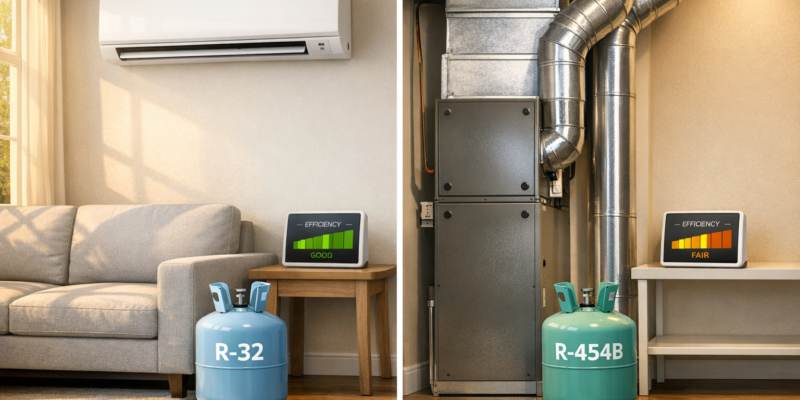
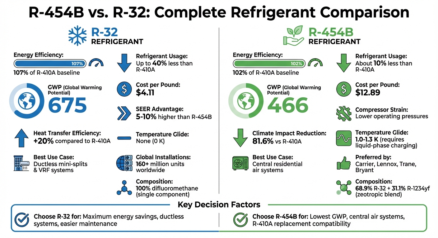
- R-32: Offers higher energy efficiency (107% of R-410A baseline) and requires up to 40% less refrigerant. It’s widely used in ductless and mini-split systems and costs less at approximately $4.11 per pound. However, it has a higher Global Warming Potential (GWP) of 675.
- R-454B: Preferred for central residential systems by U.S. manufacturers like Carrier and Lennox. It has a lower GWP of 466, reducing direct emissions further but is less efficient (102% of R-410A baseline) and more expensive at $12.89 per pound.
Quick Comparison
| Feature | R-32 | R-454B |
|---|---|---|
| Efficiency | 107% of R-410A baseline | 102% of R-410A baseline |
| Refrigerant Usage | Up to 40% less | About 10% less |
| GWP | 675 | 466 |
| Cost per Pound | $4.11 | $12.89 |
| Best Use Case | Ductless systems | Central air systems |
R-32 is ideal for maximizing energy savings, while R-454B is a better choice for those prioritizing lower GWP in central air systems.
R-454B vs R-32 Refrigerant Comparison Chart
A2L Refrigerants. 454B vs R32 – Which is Better?
sbb-itb-99db659
Technical Specifications and Properties of R-454B and R-32
As the push for energy efficiency reshapes refrigerant choices, it’s important to understand the technical differences between R-454B and R-32. R-32 is composed entirely of difluoromethane, while R-454B is a zeotropic blend made up of 68.9% R-32 and 31.1% R-1234yf. This compositional difference impacts how these refrigerants behave in systems, especially during charging and maintenance.
One key distinction lies in temperature glide. R-32 has no temperature glide, making it straightforward to handle. On the other hand, R-454B has a glide of 1.0–1.3 K, which demands precise liquid-phase charging. If an R-454B system develops a leak, the components may escape unevenly, often necessitating a complete recharge instead of just topping off. This is not typically an issue with R-32 systems. These characteristics underline the need for a deeper technical comparison.
Technical Comparison of R-454B and R-32
Although both refrigerants share the same critical temperature of 78.1°F (172.6°F), their operational traits differ. R-32 operates at pressures similar to R-410A and provides around 20% better heat transfer efficiency. Meanwhile, R-454B’s slightly reduced operating pressures ease compressor strain and make it a closer match for R-410A systems.
These performance differences are reflected in efficiency and capacity. R-32 systems achieve efficiency ratings over 107% compared to R-410A, with a capacity boost exceeding 110%. In contrast, R-454B systems typically reach about 102% efficiency and a capacity increase of 97%. Additionally, R-32 systems require up to 40% less refrigerant than R-410A systems, while R-454B systems need about 10% less.
Environmental Impact of Both Refrigerants
The environmental performance of these refrigerants is another critical factor. Both meet the EPA AIM Act’s GWP (Global Warming Potential) limit of 750, but R-454B has a GWP of 466, which is roughly 31% lower than R-32’s GWP of 675. This translates into significant reductions in direct emissions: R-454B cuts climate impact by 81.6% compared to R-410A, while R-32 achieves a 73.6% reduction. Both refrigerants also have an Ozone Depletion Potential (ODP) of zero, ensuring they don’t harm the ozone layer.
However, the broader environmental impact extends beyond direct emissions. Indirect emissions from energy usage make up 70% to 80% of an HVAC system’s total carbon footprint, while refrigerant emissions account for less than 20%. As Daikin explains:
R-32 refrigerant’s increased efficiency helps OEM engineers design systems with low electricity consumption over the system’s life, compensating for Direct Emissions.
Energy Efficiency Performance of R-454B and R-32
When comparing R-32 and R-454B, R-32 generally comes out ahead in energy efficiency. Lab tests conducted under identical conditions show that R-32 systems deliver 5–10% higher SEER ratings than R-454B systems. This translates into noticeable savings on electricity bills over the lifespan of an HVAC system. Considering that energy consumption makes up 70–80% of an HVAC system’s total carbon footprint, the efficiency edge of R-32 carries significant weight. Let’s break down how these refrigerants stack up in terms of energy performance.
R-32: High Heat Transfer Efficiency
R-32 owes its strong performance to its thermodynamic properties, which improve heat transfer by around 20% compared to R-410A. This advantage becomes even more critical during heat waves, as R-32 systems tend to maintain consistent performance better than R-454B systems. This reliability during peak grid demand makes R-32 an attractive choice for extreme temperature conditions.
In practical applications, the efficiency of R-32 is clear. For example, commercial R-32 VRF (Variable Refrigerant Flow) and rooftop systems can achieve up to 12% energy savings in large-scale environments like retail stores and office buildings. Additionally, its higher volumetric capacity allows for more compact system designs. As of May 2025, the average cost for installing a 3-ton R-32 mini-split system was approximately $3,500, compared to $4,000 for a 3-ton R-454B central air system. These factors make R-32 a compelling option for maximizing energy efficiency and reducing costs.
R-454B: Balancing Efficiency and Environmental Goals
R-454B, while slightly less efficient than R-32, offers its own set of benefits, including a low Global Warming Potential (GWP) of 466. Its lower operating pressures help reduce strain on the compressor, potentially extending the lifespan of equipment.
“R-454B bridges the gap between ‘regulatory compliance’ and ‘performance utility,’ laying the foundation for the next decade of HVAC development.”
In 2025, homeowners using Carrier’s R-454B-optimized Infinity systems reported cutting their electricity bills by about 15% compared to older units. R-454B also showed strong performance in the U.S. Department of Energy‘s Cold Climate Heat Pump Challenge, where it excelled in extreme heating scenarios. For residential central air systems replacing R-410A units, R-454B offers a practical upgrade with measurable energy and environmental benefits.
Case Study: Residential vs. Commercial Energy Savings
The market adoption of these refrigerants highlights their unique strengths. R-32 is a top choice for ductless systems, thanks to its efficiency and compact design. On the other hand, R-454B is better suited for central air systems, as it works seamlessly with scroll compressors and closely matches the operating characteristics of R-410A.
Leading U.S. manufacturers like Carrier, Lennox, and Bryant have leaned toward R-454B for residential central air systems. Meanwhile, international brands such as Daikin and Mitsubishi have favored R-32 for their products. Daikin, for instance, has deployed over 160 million R-32 units worldwide as of 2024, proving its long-term effectiveness and reliability across a variety of climates. These trends underscore the importance of choosing the right refrigerant for the specific application to achieve the best energy efficiency and cost savings.
Choosing Between R-454B and R-32 for Your HVAC System
Picking the right refrigerant for your HVAC system depends on several factors, including your system type, the expertise of local contractors, and your maintenance priorities. Both R-32 and R-454B meet modern efficiency standards, but they excel in different scenarios. Knowing where each refrigerant fits best can help you save money and reduce maintenance headaches.
Availability and Market Adoption
R-32 has an extensive global presence, with over 160 million units installed worldwide by 2026. It’s particularly dominant in ductless mini-split and VRF (Variable Refrigerant Flow) markets, with brands like Daikin, Mitsubishi, and LG leading the charge. On the other hand, R-454B has gained traction among major U.S. manufacturers such as Carrier, Lennox, and Trane for central residential systems.
A 2025 survey revealed that 63% of U.S. contractors prefer R-454B for whole-home systems, while 70% favor R-32 for ductless setups. One notable distinction is that R-32 is widely available and produced by multiple manufacturers, whereas R-454B is a proprietary blend. If you’re considering R-32 for a central system, ensure your local HVAC contractors are certified to handle A2L refrigerants.
Beyond market trends, system compatibility is a critical factor when deciding between these refrigerants.
System Compatibility and Maintenance
Neither R-32 nor R-454B can replace older refrigerants like R-410A or R-22 directly. Both require systems specifically designed for A2L refrigerants, which are mildly flammable. These systems must also include safety sensors and use synthetic POE oil.
R-32’s single-component design makes recharging simpler, while R-454B’s blend requires careful liquid-phase charging to prevent fractionation. If you plan to reuse copper piping from an older system, a professional flush is essential to remove residual mineral oil.
It’s also worth noting the difference in compressors: R-454B systems are often paired with scroll compressors, common in U.S. central air systems, while R-32 systems typically use rotary compressors.
Cost Implications and Long-Term Benefits
R-32 systems generally come with lower upfront costs and achieve higher SEER (Seasonal Energy Efficiency Ratio) ratings. Meanwhile, R-454B’s lower GWP (Global Warming Potential) might justify its higher price tag for some users. R-32 systems require up to 40% less refrigerant compared to R-410A systems, while R-454B systems use about 10% less. Additionally, R-32 systems typically achieve 5% to 10% higher SEER ratings, which translates to reduced electricity bills over time.
“R-32 refrigerant’s increased efficiency helps OEM engineers design systems with low electricity consumption over the system’s life, compensating for Direct Emissions.”
For ductless systems, R-32 often delivers the best efficiency-per-dollar and easier long-term maintenance. In contrast, R-454B is better suited for central air replacements, offering compatibility with standard U.S. residential setups and easier servicing in areas with stricter safety regulations. These considerations play a key role in determining which refrigerant is the right fit for your HVAC needs.
Conclusion: Selecting the Right Refrigerant for Energy Efficiency
Main Differences in Energy Efficiency
Choosing between R-32 and R-454B often comes down to balancing energy efficiency with environmental priorities. R-32 stands out for its energy performance, achieving over 107% efficiency compared to R-410A, while R-454B reaches over 102% efficiency. This translates to 5% to 10% higher SEER ratings in tests. Additionally, R-32’s single-component design avoids temperature glide, making it easier to service and preventing changes in composition during leaks. On the other hand, R-454B offers a lower GWP of 466, compared to R-32’s 675, making it more aligned with tightening environmental regulations.
Cost is another factor to weigh. R-32 is priced at about $4.11 per pound, significantly less than R-454B’s $12.89 per pound. R-32’s efficiency can also result in lower electricity costs over 15 to 20 years, and it typically requires up to 40% less refrigerant, compared to R-454B’s 10% reduction. These distinctions can help determine the best refrigerant for specific needs.
Recommendations for HVAC Applications
For ductless mini-splits and VRF systems, R-32 is the top choice. It delivers superior efficiency, straightforward maintenance, and excels in high-temperature climates above 110°F. This makes it ideal for areas like inland California or Texas, where heat transfer efficiency is especially critical.
For central residential air conditioning, R-454B is a strong contender, particularly for systems from manufacturers like Carrier, Trane, or Lennox, which are optimized for this refrigerant. Its lower discharge temperatures also make it a solid option for large commercial systems, extending compressor life.
If long-term energy savings and maintenance simplicity are your priorities, R-32 is the better fit. However, if achieving the lowest possible GWP is your main goal, R-454B provides a regulatory advantage, though it comes with higher upfront costs and slightly lower efficiency. For tailored advice on the best refrigerant for your HVAC system, certified contractors at Hydrodynamics can offer expert guidance based on your specific requirements, climate, and efficiency objectives.
FAQs
Which refrigerant will lower my electric bill more?
R-32 can help lower your electric bill thanks to its higher energy efficiency and superior cooling capacity when compared to R-454B. This means HVAC systems using R-32 consume less energy while delivering better overall performance.
Can I retrofit my R-410A system to use R-32 or R-454B?
Retrofitting an R-410A system to use R-32 or R-454B isn’t a simple switch. These refrigerants have different pressure levels, chemical compositions, and compatibility requirements, meaning the system may need specific alterations to function correctly. It’s essential to work with a professional who can evaluate whether the retrofit is possible and make the necessary adjustments safely and effectively.
How does A2L flammability affect installation and servicing?
A2L refrigerants, such as R-454B and R-32, are classified as mildly flammable. This means they require extra care during installation and servicing to ensure safety. Technicians working with these refrigerants must stick to strict safety measures, including:
- Ensuring proper ventilation in the work area.
- Keeping all ignition sources far from the refrigerant.
- Wearing appropriate personal protective equipment (PPE).
Performing thorough leak checks and strictly following the manufacturer’s guidelines are key steps to reducing fire risks. While these refrigerants are known for their environmental advantages, their flammable nature means specialized training and precautions are non-negotiable for safe operation.